-
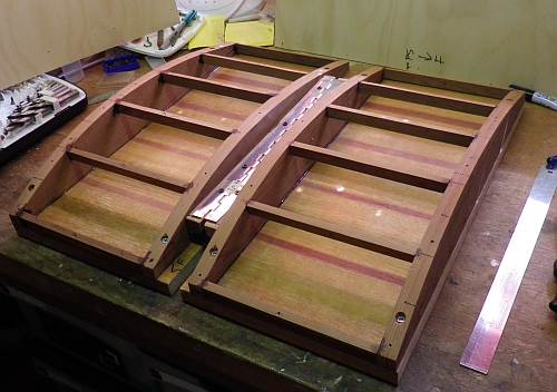
The sail building board is constructed on a 500mm X 500mm
piece of stable high density compressed board that is solid and stable.
-
Four identical ribs corresponding to the airfoil shape
chosen (I chose the 43% parabolic section outlined in the
spreadsheet) are
cut out, smoothed and screwed/glued to the board leaving a 60mm or so gap
between the centre two. The outside two are on the edge of the board.
I used 16mm board for this
-
The inner two ribs are pre-drilled for the hinges at a
position about half-way down the parabolic section (see end elevation
diagram).
-
Construct two hinges made of 8-10mm threaded rod by
making a 12mm cut out in the ends of 100mm sections and drilling and pinning
the two interlocking pieces with a 2mm steel pin.
See end of page for alternative hinge
-
Fit the two hinges and secure using four nuts for each
hinge. Ensure that the pin is precisely in the centre of the space
between the two inner ribs and that the pivot pin is horizontal.
Make sure there is no force on the hinge pulling or pushing the ribs.
-
Cut out the cross supports carefully and glue them in
place with an epoxy glue ensuring their upper surface is parallel to the rib
surface at their intersection.
-
When you are satisfied with all the previous steps mark
the centre of the board on the bottom surface and while inverted cut the
base board into two by making two cuts 5mm or so either side of the centre
line.
-
Work from now on must be carried out on a flat firm table
or bench. The board should now pivot up in the middle in a firm but
controlled way
-
Cut two thin 3-5mm thick ply or similar sheets to cover
the two sides of the board. Each will be just larger than 250 mm X
500mm. To reduce the tension on the board and to make the ply sit
easily over the parabolic curve, I pre-bent the ply by gently spraying its
surface with water and adding weights to the centre whilst supporting the
ends with blocks of timber. I repeated the moisture a couple of times
and left the ply in the bent position for a week or so to make sure it was
completely dry.
-
Before securing the ply to the ribs/cross pieces the ends
of the ply where they meet in the middle will need to be shaped slightly as
the pivot position is higher than the ply at the front and rear ends of the
parabola. You can gauge how much to remove by test fitting the pieces
on the board and raising the middle of the base board by 20mm or so. (There
should be no need to ever raise it above that amount - probably 15mm would
be OK)
-
Secure the ply to the ribs and cross pieces using screws
starting in the middle and working out. The pre-bending will make this
much easier. Make absolutely sure that the two ply covers are touching
in the middle and that they are in line with the hinge points. I chose
not to glue the ply down in case I had to later make alterations to the
hinges. Inspection holes could be made through the bottom base as an
alternative and the ply glued in place.
-
I draw guide lines across the surface with a thin
permanent marker or biro at the 43% maximum curvature point and in pairs
either side of this at equivalent distances so the lines represent where a
seam would reach. I number these pairs and have about 6 of them.
This makes it easy to lay a seam between the lines of the same number and
ensures the maximum camber is at 43%. Distances for these lines can be
deduced from the Sail
Curve Analysis spreadsheet
-
The surface needs to be sealed and smoothed. I used
two coats of epoxy resin with a small amount of filler added and spread the
thin mixture with a plastic straight edge. Sand the surface to a clear
smooth finish. The guide lines show quite well through this finish.
-
I made small blocks to go at the four corners of each
base piece to act as pivot points for the lifting action required at the
centre.
 STIRLING MARBLEHEAD YACHT RACING CLUB
Inc.
STIRLING MARBLEHEAD YACHT RACING CLUB
Inc. SAIL MAKING - Building Board Construction